
Capacitor
SYLLABUS
Capacitance and capacitor, Parallel plate capacitor, Combination of capacitors, Energy of charged capacitor, Effect of a dielectric Polarization and displacement.
What is This Chapter About?
Every electronic device you use — your smartphone, laptop, television, radio, camera — contains capacitors. They store energy in camera flashes, smooth out voltage fluctuations in power supplies, tune radio receivers, filter signals in audio amplifiers, and store charge in memory circuits. The capacitor is one of the most fundamental and ubiquitous components in all of electronics.
Chapter 22 of NEB Grade 11 Physics develops the complete theory of capacitors — what they are, how they store charge and energy, how their capacitance is calculated, how multiple capacitors combine, and what happens when a dielectric material is inserted between their plates. Carrying 7 teaching hours — one of the highest in Grade 11 — this is a mathematically rich chapter with direct connections to both electrostatics and practical electronics.
Key Concepts You Will Learn
Capacitance and the Capacitor
A capacitor is a device that stores electric charge. In its simplest form, it consists of two conducting plates separated by an insulating gap (air or a dielectric material). When connected to a battery, charge builds up on the plates — positive on one, negative on the other — until the potential difference across the plates equals the battery voltage.
The capacitance (C) of a capacitor is defined as the ratio of the charge stored to the potential difference across it:
[latex]C = \frac{Q}{V}[/latex]
Capacitance measures how much charge a capacitor can store per unit of potential difference. The SI unit of capacitance is the farad (F) = coulomb per volt (C/V). In practice, most capacitors have capacitances in the range of microfarads ([latex]\mu F = 10^{-6}[/latex] F), nanofarads (nF = [latex]10^{-9}[/latex] F), or picofarads (pF = [latex]10^{-12}[/latex] F) — a farad is an enormous capacitance.
Capacitance is a geometric property — it depends on the size, shape, and separation of the conducting plates and the material between them, not on the charge or voltage. The capacitance of a capacitor is a constant for a given physical configuration.
Parallel Plate Capacitor
The most important and commonly studied capacitor is the parallel plate capacitor — two large, flat conducting plates of area A separated by distance d. Using Gauss’s Law to find the field between the plates ([latex]E = \frac{\sigma}{\epsilon_0} = \frac{Q}{\epsilon_0 A}[/latex]) and the relation V = Ed:
[latex]C = \frac{\epsilon_0 A}{d}[/latex]
This elegant result shows that capacitance increases with plate area (larger plates store more charge at the same voltage) and decreases with plate separation (closer plates create stronger fields for the same voltage, requiring less charge for a given p.d.). Doubling the area doubles C; doubling the separation halves C.
Effect of Dielectric
When an insulating material — called a dielectric — is inserted between the plates of a capacitor, the capacitance increases by a factor equal to the relative permittivity (or dielectric constant) [latex]\epsilon_r[/latex] of the material:
[latex]C = \frac{\epsilon_r \epsilon_0 A}{d} = \frac{\epsilon A}{d}[/latex]
where [latex]\epsilon = \epsilon_r \epsilon_0[/latex] is the absolute permittivity of the dielectric.
The increase in capacitance occurs because the dielectric material becomes polarised in the electric field — the positive and negative charges within each molecule shift slightly in opposite directions, creating tiny electric dipoles aligned with the field. These dipoles produce their own internal electric field that partially opposes the external field, reducing the net field between the plates. For the same charge Q, a weaker field means a lower potential difference V, and since [latex]C = \frac{Q}{V}[/latex], the capacitance increases.
Dielectrics also prevent electrical breakdown (sparking between plates) and allow plates to be placed very close together without touching, enabling very high capacitances in compact sizes. Common dielectrics include ceramic, mica, polyester film, and electrolytic solutions.
Capacitors in Series
When capacitors are connected in series (end to end, so the same charge flows to each), the total capacitance [latex]C_s[/latex] satisfies:
[latex]\frac{1}{C_s} = \frac{1}{C_1} + \frac{1}{C_2} + \frac{1}{C_3} + \ldots[/latex]
The total capacitance of series capacitors is always less than the smallest individual capacitance. In series, the same charge Q accumulates on each capacitor, but the total voltage is divided between them — capacitors in series act as voltage dividers.
Capacitors in Parallel
When capacitors are connected in parallel (side by side, so the same voltage appears across each), the total capacitance [latex]C_p[/latex] is simply the sum:
[latex]C_p = C_1 + C_2 + C_3 + \ldots[/latex]
Parallel connection always gives a larger total capacitance than any individual capacitor. Each capacitor stores different charge (proportional to its capacitance) but experiences the same voltage — capacitors in parallel act as charge accumulators.
Energy Stored in a Charged Capacitor
When a capacitor is charged, work is done moving charge from one plate to the other against the growing potential difference. This work is stored as electrical potential energy in the electric field between the plates. The energy can be derived by calculating the total work done charging from 0 to final charge Q:
[latex]U = \frac{1}{2}QV = \frac{1}{2}CV^2 = \frac{Q^2}{2C}[/latex]
All three forms are equivalent and useful in different situations. The energy is stored in the electric field between the plates, with an energy density (energy per unit volume) of:
[latex]u = \frac{1}{2}\epsilon_0 E^2[/latex]
This energy is released when the capacitor discharges — as in a camera flash, which stores energy slowly from a battery and releases it explosively in a fraction of a second through the flash lamp.
Polarisation and Displacement in Dielectrics
At a deeper level, when a dielectric is placed in an electric field, the displacement of charges within molecules creates a polarisation P — a net dipole moment per unit volume of the material. The electric displacement D = [latex]\epsilon_0 E + P = \epsilon E[/latex] is introduced as a quantity that depends only on free charges (not bound charges in the dielectric). These concepts connect electrostatics in materials to the broader framework of electromagnetic theory.
Why This Chapter Matters for NEB Exams
Capacitor is one of the most heavily examined topics in NEB Grade 11 Physics. Derivation of the capacitance of a parallel plate capacitor, the effect of a dielectric, and the formula for energy stored are classic long-answer questions. Numerical problems on series and parallel combinations — finding equivalent capacitance, charge on each capacitor, and voltage across each — appear in virtually every board paper. The energy stored formula [latex]U = \frac{1}{2}CV^2[/latex] and its applications are standard examination topics. The physical explanation of how a dielectric increases capacitance through polarisation is a frequent conceptual question.
Important Topics to Focus On
- Definition of capacitance: [latex]C = \frac{Q}{V}[/latex] — unit (farad) and physical meaning
- Uses of capacitors in simple circuits
- Parallel plate capacitor derivation: [latex]C = \frac{\epsilon_0 A}{d}[/latex]
- Effect of changing A and d on capacitance
- Dielectric materials — definition, relative permittivity, and effect on capacitance
- Physical explanation of dielectric effect through polarisation
- Capacitors in series: [latex]\frac{1}{C_s} = \sum \frac{1}{C_i}[/latex] — derivation and numerical problems
- Capacitors in parallel: [latex]C_p = \sum C_i[/latex] — derivation and numerical problems
- Energy stored: [latex]U = \frac{1}{2}CV^2 = \frac{1}{2}QV = \frac{Q^2}{2C}[/latex] — derivation and applications
- Energy density in electric field: [latex]u = \frac{1}{2}\epsilon_0 E^2[/latex]
- Polarisation and electric displacement in dielectrics
- Numerical problems on all combination and energy topics
Connection to Other Chapters
Capacitor builds directly on Chapter 20 (Electric Field) — the uniform field between parallel plates — and Chapter 21 (Potential) — capacitance is defined through potential difference and energy is [latex]\frac{1}{2}QV[/latex]. Chapter 23 (DC Circuits) uses capacitors as circuit components. In Grade 12, Chapter 19 (Alternating Currents) treats capacitors in AC circuits through capacitive reactance [latex]X_C = \frac{1}{\omega C}[/latex] and series RLC resonance. Chapter 18 (Electromagnetic Induction) presents an exact parallel — energy stored in an inductor [latex]\frac{1}{2}LI^2[/latex] mirrors [latex]\frac{1}{2}CV^2[/latex] for a capacitor, revealing the deep symmetry between electric and magnetic energy storage. The dielectric permittivity [latex]\epsilon_r[/latex] connects to Grade 12 Chapter 17 (Magnetic Properties of Materials) — where magnetic permeability [latex]\mu_r[/latex] plays the exactly analogous role for magnetic materials.
Capacitors:
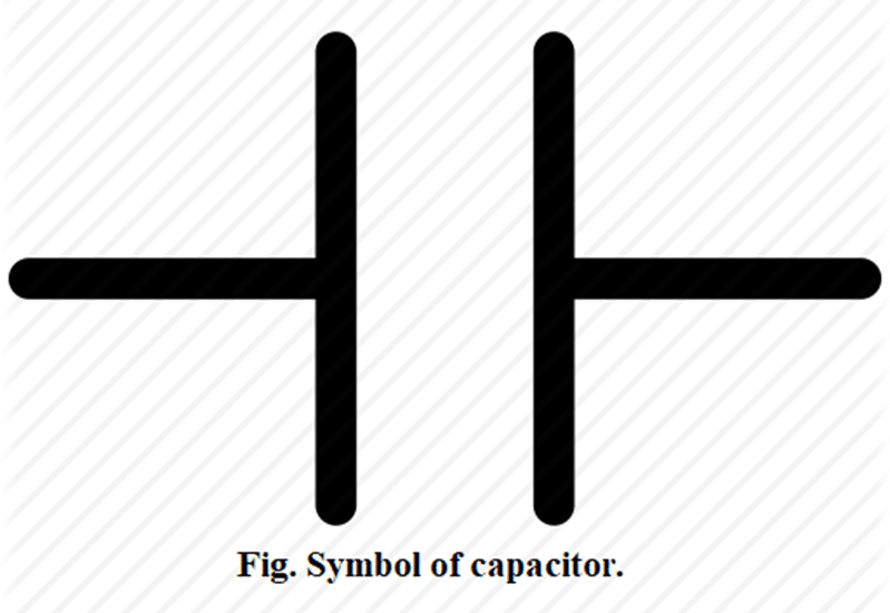
A capacitor is a device which store electric charges on it. Basically, it consists of 2 conducting surfaces separated by an insulating material or vacuum. The conducting surfaces are called plates and the insulating materials are called di – electric. There are various types of capacitors.
Capacitance of a capacitor:
The charge holding capacity of a capacitor is called its capacitance. When charge is given to the capacitor, the potential difference between the plates increase. If Q be the charge on either plate of the capacitor and V be the potential difference across the plates of the capacitor, then, it is given that,
[latex]Q \propto V[/latex].
Or, [latex]Q = CV[/latex], where, C is a constant called capacitance of a capacitor.
We have, [latex]C = Q/V[/latex]. Hence, the capacitance of a capacitor may be defined as the ratio of charge on either plate of the capacitor to the potential difference of the capacitor. The unit of capacitance is [latex]CV^{-1}[/latex] or Farad (F).
From the relation,
[latex]C = Q/V[/latex].
The capacitance of a capacitor is said to be 1 Farad if its potential difference rises by 1V when a charge of 1C is given to it. The smaller units of the capacitance are mF, μF (micro Farad), nF (nano Farad), where,
1 mF = [latex]10^{-3}[/latex] F
1 μF = [latex]10^{-6}[/latex] F
1 nF = [latex]10^{-9}[/latex] F
You've reached the end of the free preview. Continue with NN Premium.
- Complete access to every Premium chapter
- Notes, QBank, solutions & MCQs
- Premium PDFs & study resources
- Entrance preparation & mock tests
One NN Premium subscription unlocks everything.
A 300 V battery is connected across capacitors of 3μF and 6 μF in parallel. calculate the energy stored in each capacitor.
Solution
Emf (V) = 300 V
C₁ = 3μF = [latex]3\times 10^{-6}F[/latex]
C₂ = 6 μF = [latex]6\times 10^{-6}F[/latex]
Energy stored in capacitor 1 (E₁) = [latex]\frac{1}{2}C_1V^2 = \frac{1}{2}\times(3\times 10^{-6})\times(300)^2 = 0.135\ J[/latex]
Energy stored in capacitor 2 (E₂) = [latex]\frac{1}{2}C_2V^2 = \frac{1}{2}\times(6\times 10^{-6})\times(300)^2 = 0.27\ J[/latex]
A parallel plate air capacitor of capacitance [latex]245\times 10^{-12}F[/latex] has a charge of magnitude 0.148 μC on each plate. Find the potential difference and electric field intensity between the plates if the distance between plates is 5 mm.
Solution
Capacitance (C) = [latex]245\times 10^{-12}F[/latex]
Charge (q) = 0.148 μC = [latex]0.148\times 10^{-6}C[/latex]
Potential difference (V) = ?
Electric field intensity (E) = ?
Distance between plates (d) = 5 mm = [latex]5\times 10^{-3}m[/latex]
You've reached the end of the free preview. Continue with NN Premium.
- Complete access to every Premium chapter
- Notes, QBank, solutions & MCQs
- Premium PDFs & study resources
- Entrance preparation & mock tests
One NN Premium subscription unlocks everything.